


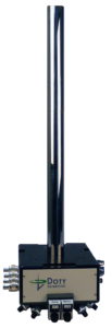
The Fluorine-Quad-MAS, H/F/X/Y
4 channels, one a dedicated 19F Channel
Full line of Solids NMR Probes
Over 30 years of High Temperature and Low Temperature Nuclear Magnetic Resonance, both MAS and Wideline.
1H or Dual Frequency H/X or H/F
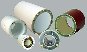
3 T to 14.1 T MRI Simple-Tune RF
Pre-clinical and Research Coils
Let us improve your MRI results with our single frequency or dual-tuned MRI rf Volume Coil Modules, and a wide variety of Surface Coils.
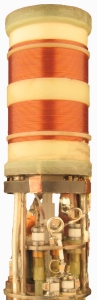
PFG/Diffusion Z-gradient Probe
Measure the lowest diffusion coefficients
Largest sample region with 1% gradient uniformity
Now PFG – Z gradient NMR probes or Liquids NMR probes up to 300 C
